Under the brand name IO-Link there is a communication system for the connection of intelligent sensors and actuators to an automation system standardized in IEC 61131-9 under the designation Single-drop digital communication interface for small sensors and actuators (SDCI). The standardization covers both the electrical connection data and a digital communication protocol through which the sensors and actuators exchange data with the automation system.
An IO-Link system consists of an IO-Link master and one or more IO-Link devices, i.e. sensors or actuators. The IO-Link master provides the interface to the higher-level controller (PLC) and controls communication with the connected IO-Link devices.
An IO-Link master can have one or several IO-Link ports, but only one IO-Link device can be connected to each port, although cascaded devices or hubs are now also available.
An IO-Link device can be an intelligent sensor, actuator or e.g. a hub, and devices such as power supplies with IO-Link connectivity are also on the market. Intelligent means in relation to IO-Link that a device has e.g. a serial number or parameter data (e.g. sensitivities, switching delays or characteristic curves) that can be read or written via the IO-Link protocol. Changing parameters can thus in part be performed at runtime by the PLC. IO-Link and the data transmitted with it are often used to carry out preventive maintenance and servicing; for example, it is possible to configure an optical sensor so that it reports via IO-Link when it is about to become dirty and requires cleaning, which then does not have to be performed unnecessarily early or too late as before.
The parameters of the sensors and actuators are device-specific, so there is parameter information for each device in the form of an IODD (IO Device Description). [Source: Wikipedia]
Sensor vs. IO-Link Sensor (Devices) Non-IO-Link sensors have no built-in logic to react to their environment. For example, if a sensor becomes dirty, the degree of contamination will continue to increase until the sensor fails.
An IO-Link sensor, on the other hand, can determine the degree of contamination, adjust the sensor parameters during operation and initiate further steps to clean the contamination. After cleaning, automatic parameterization is performed again.
Further advantages of IO-Link
Standardized according to IEC 61131-9
Manufacturer-independent integration into fieldbus
Supports connections (3-wire - 2x power & 1x signal) according to the following standards:
- M5
- M8
- M12
- Three-wire cables
Bidirectional communication for device analysis
Support for the following speeds
- 4.8kBaud (1 Baud = 1 symbol per second)
- 38.4kBaud
- 230.4kBaud
High Level Architecture 
At each point of the master, only one IO-Link device is connected, i.e. there is point-to-point communication between the device (e.g. sensor) and the master.
IODD The IODD (IO Device Description) describes sensors and actuators. It contains information on identification, device parameters, process and diagnostic data, communication properties and the structure of the user interface in engineering tools. It consists of several files: a main file and optional external language files (both in XML format), and optional image files (in PNG format). [Source: Wikipedia]
The IODD for individual devices or sensors can be obtained either from the manufacturer’s website or from a central repository: https://ioddfinder.io-link.com
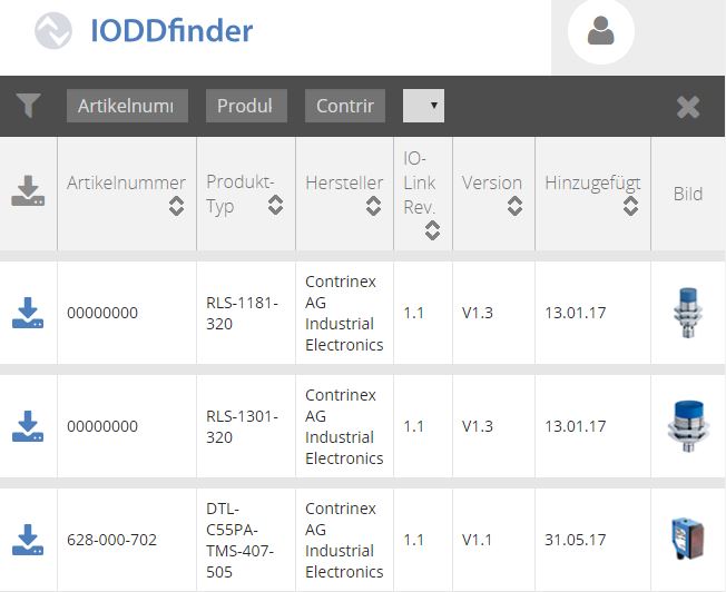
After downloading the IODD *.zip file, the device data is made available within an *.xml file. The name of the *.xml file can be chosen freely. 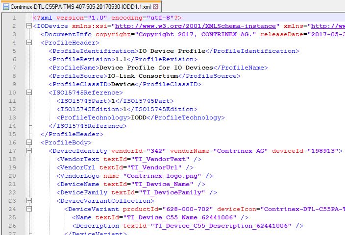
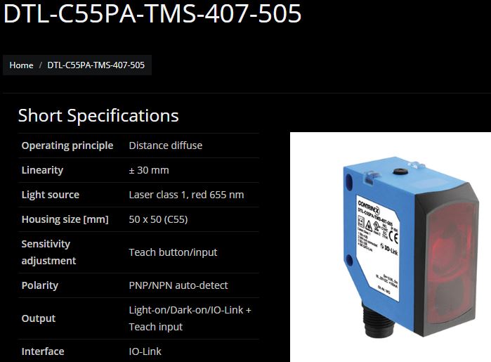
The above and the following code examples refer to the DTL-C55PA-TMS-407-505 sensor from Contrinex. IODD Download Link.
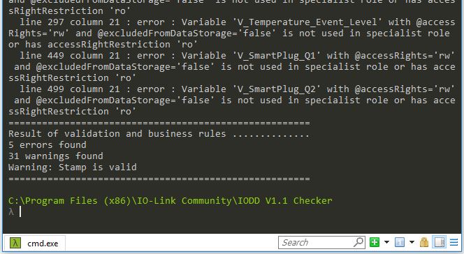
IODDChecker The IODD file can be validated via the command line using the application IODDChecker: 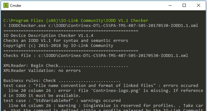
IODD Structure The basic structure looks as follows: 
As can be seen in the illustration, the basic structure consists of the following six components:
- DocumentInfo (optional)
- ProfileHeader
- ProfileBody
- CommNetworkProfile
- ExternalTextCollection
- Stamp
1. DocumentInfo 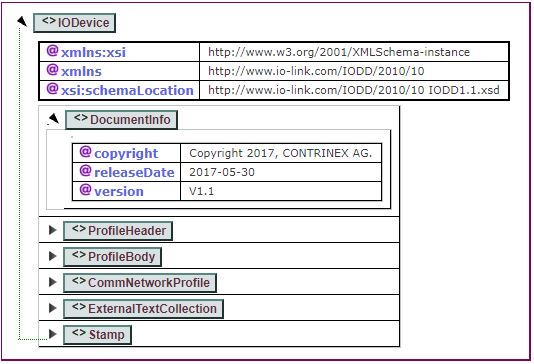 All fields are optional and are self-explanatory.
2. ProfileHeader 

Example: [codesyntax lang=“xml”]
<ProfileHeader>
  <ProfileIdentification>IO Device Profile</ProfileIdentification>
  <ProfileRevision>1.1</ProfileRevision>
  <ProfileName>Device Profile for IO Devices</ProfileName>
  <ProfileSource>IO-Link Consortium</ProfileSource>
  <ProfileClassID>Device</ProfileClassID>
  <ISO15745Reference>
    <ISO15745Part>1</ISO15745Part>
    <ISO15745Edition>1</ISO15745Edition>
    <ProfileTechnology>IODD</ProfileTechnology>
  </ISO15745Reference>
</ProfileHeader>
[/codesyntax]
3. ProfileBody Here the device-specific information is listed. 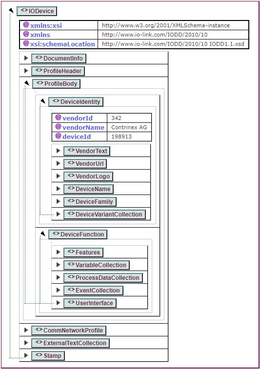
DeviceIdentity
- vendorId: vendor ID
- vendorName: vendor name
- deviceId: vendor or internal device ID
- VendorText: vendor description
- VendorUrl: vendor URL
- VendorLogo: PNG 160x90
- DeviceName: device name
- DeviceFamily: vendor or internal device classification
- DeviceVariantCollection: describes the different variants of a product.
By combining ‘vendorId’ & ‘deviceId’, you can determine whether an IODD is for a new or already existing device.
DeviceFunction describes the full functionality of a device.
- Features: describes the standard functions of the device
- blockParameter: is block parameter support available? (true/false)
- dataStorage: can the device store data? (true/false)
- profileCharacteristic: list of supported PIDs (Profile Identifiers)
- SupportedAccessLocks: ways to access the device
- VariableCollection: all variables supported by the device
- ProcessDataCollection: all data processed by the device
- EventCollection: all events supported by the device, e.g. warnings
- UserInterface: all device menus
4. CommNetworkProfile Describes the communication of the IO-Link interface. 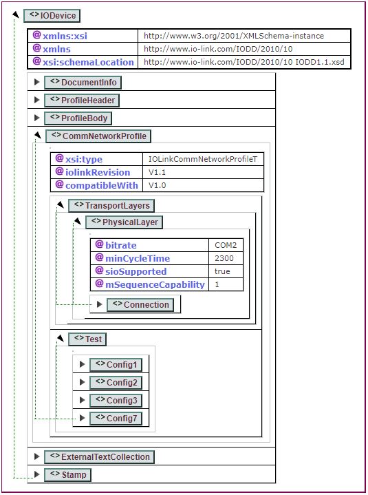
- iolinkRevision: the implemented protocol version
- compatibleWith: specified only if the device is compatible with IO-Link 1.0
- TransportLayers
- PhysicalLayer
- bitrate: allowed are COM1-COM3
- minCycleTime: ….
- sioSupported: an IO-Link sensor starts by default in SIO mode (standard I/O mode). Therefore, digital IO-Link communication must be started actively.
- mSequenceCapability: ….
- Test: information for automatic testing
- PhysicalLayer
- ExternalTextCollection: comparable to a language property file
- Stamp: IODDChecker knows the two modes ‘check’ & ‘stamp’. In ‘check’ mode, found errors are reported but the file is not overwritten. In ‘stamp’ mode, the stamp is renewed, i.e. the file is modified.